There is one man whose hour-long sessions in my company give me days of stress and worry. He can be found in a soundless and windowless room deep in the bowels of an anonymous building in a town on the outskirts of London. You’ve probably driven past it or others like it worldwide, without being aware of the sinister instruments that lie within.
The man in question is sometimes there to please the demands of the State, but there’s nothing too scary about him. Instead he’s an engineer and expert in electromagnetic compatibility, and the windowless room is a metal-walled and RF-proof EMC lab lined with ferrite tiles and conductive foam spikes. I’m there with the friend on whose work I lend a hand from time to time, and we’re about to discover whether all our efforts have been in vain as the piece of equipment over which we’ve toiled faces a battery of RF-related tests. As before when I’ve described working on products of this nature the specifics are subject to NDAs and in this case there is a strict no-cameras policy at the EMC lab, so yet again my apologies as any pictures and specifics will be generic.
There are two broadly different sets of tests which our equipment will face: RF radiation, and RF injection. In simple terms: what RF does it emit, and what happens when you push RF into it through its connectors and cables? We’ll look at each in turn as a broad overview pitched at those who’ve never seen inside an EMC lab, sadly there simply isn’t enough space in a Hackaday article to cover every nuance.
RF Emissions Testing

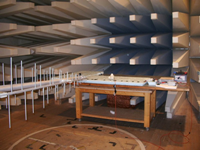
The interior of a typical EMC lab showing the RF-absorbing baffles on the wall, the equipment under test on a wooden table, and a wideband log-periodic antenna. Techie2 [CC-BY-SA-3.0 ], via Wikimedia Commons.The process of RF emissions testing is a surprisingly simple one in theory, though the calibrated instruments and EMC lab required to do it are extremely expensive. The equipment under test is placed on an RF-transparent wooden or plastic table in the centre of the lab, powered up, and a wideband antenna is pointed at it. The lab is then closed, and in the control room a sensitive calibrated receiver is stepped through its frequency range with the signal level detected at each frequency recorded by a computer.
In the lab itself the table is often mounted on a turntable and the antenna on a moveable gantry, such that the test can include measurements from all angles. A variety of antennas are likely to be used depending on the frequency, but you would expect to see a log-periodic antenna for use from HF up to UHF (about 1MHz to about 500MHz), and a Vivaldi antenna from UHF into the many GHz microwaves.
The test itself takes a few minutes as the computer does its GPIB magic, and the result you are given is a graph of intensity versus frequency with that crucial pass/fail red line over which your intensity trace must not stray. You’ll see quite a few intensity peaks, and you’ll find they will often correspond to internal clocks or data rates.

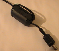
This chunky ferrite probably means someone was defeated by the EMC lab. AlexJFox [Public domain], via Wikimedia Commons.It’s quite likely your device will fail somehow, that’s the way it is. There will be a peak somewhere over the line, and looking at its frequency you’ll have an inking what’s causing it. At this point you reach for the pile of accessories you brought along, and set to work trying to fix it. Copper tape over all possible joints in the casing that might leak a bit or RF, and all the ferrite chokes and clamps and rings and beads you could carry. These you’ll apply to your cables, as well as to the internal wiring in an effort to find where the radiation is being generated. Though we’re all used to seeing ferrites moulded onto our electronic accessories — and I’ll hazard a guess most of them are there to solve intractable EMC problems — it’s by no means a certainty they’ll have to stay. Once you’ve identified the source of the problem you can return to your PCB and try to design away the source rather than quash it with extra ferrite.
It’s worth saying at this point that the most valuable feature of the EMC lab is its operator. Time in there isn’t cheap, but the guidance of a really helpful expert can make the difference between leaving with a device you can make pass the test and one that has no hope. You canlearnfrom those people, as well as benefit from their advice.
RF Injection Testing
The other side of the RF testing coin are the injection tests. In simple terms, you are inducing large amounts of RF energy in all inputs to your device, and ideally you are hoping that it will neither be damaged or its operation compromised by this mistreatment. For instance, will AM modulation break through into any of your analogue circuits, will your processor reset itself, or will your digital data I/O be interrupted?

Lüthi RF injection clamps, from the Lüthi AG website (Fair use).
There are a variety of means used to induce the RF in your device, so the one I’m describing is merely the one I’m most familiar with. The Lüthi RF injection clamp is a long and narrow hinged box which when opened reveals a row of bisected ferrite cores that mate when the lid is closed. The cable is aligned with the centre of the cores, and held in place by spring lips built into the lid. There is an RF socket on the back that is coupled into the cores, making the device a very large and extremely wideband directional coupler.
The clamp is placed on an earthed ground plane and connected via an RF power amplifier to a signal generator, and a power meter is used to measure both the input power, and during calibration the induced power in a terminated wire passing through the clamp. The test requires an induced voltage of 3V RMS, so once the system has been calibrated the computer can alter the level from the signal generator to maintain this over different frequencies. A typical test will involve a scan of frequencies from the low kHz to around 100 MHz, with close observation for unusual behaviour from the device under test. A failure sends you running yet again for your stock of ferrites, with the added weapon of extra capacitive decoupling or sometimes simply screening. If you are lucky you can get to the bottom of any problems with a bit of clever design, if you are not luck you may have to accept adding theHuge Ferrite Of Shameon your cables.
There is something of a black art to designing out and fixing stray RF and EMC problems. RF never behaves in an orderly manner, or indeed as you expect it to. But learning something of the testing procedure or better still seeing the tests in action is a great help and goes a long way towards understanding more about the problem. Though I’m no EMC guru I first stood in an EMC lab in the early 1990s, and Ialwayscome away from the experience having learned something new!
If you enjoyed this article you should also check out [Bob Baddeley’s] piece on preparing a design for FCC certification.

 My Message
 Suggestions


eb
2/5/2017 3:50:49 PM
I must say you have very interesting posts here.