My Message
 Suggestions


1. Resistor
I think every engineer knows resistor. And there is a saying goes “Resistance is the most commonly used element in electronic circuits.”
Because of the resistance of a substance to current, so it is called the resistance material. Resistance will result in a change in electron flux, and the smaller the resistance, the larger the electron flux, and vice versa. Materials with no resistance or small resistance are called electric conductors. The substance that cannot forms current transmission is called electric insulator.
In physics, Resistance is used to indicate the degree of a conductor to current. The greater the resistance of the conductor, the greater the resistance of the conductor to the current. For different conductors, their resistance is generally different, and resistance is a property of the conductor itself. A resistance element is an energy-consuming element that ACTS as a barrier to current.
The resistance value of the element is normally associated with temperature, the size of the measure of the resistance will be affected by temperature parameters, defined as the temperature rise per 1 ℃ when the percentage of resistance to change.
Resistance in a circuit is represented by "R" plus a number, e.g., R1 represents a resistance numbered 1. The main functions of resistance in the circuit are shunt, current limiting, partial pressure, offset, etc.
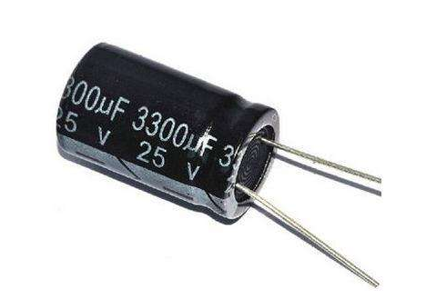
2. Capacitance
The identification method of capacitance is basically the same as that of resistance. There are three methods: direct marking, color marking and number marking.
The basic units of capacitance are expressed in farad (F), and other units are: MMF, uF, nF, pF. Including 1: ferrari = 103 = 106 micro method = 109 = 1012 skin method of large capacity capacitance on capacitance directly to mark its capacity values, such as 10 uF / 16 v capacity small capacitance of the capacity value with letters or Numbers on the capacitance letter notation: 1 m = 1000 uF p2 = 1.2 PF 1: n = 1000 PF digital representation commonly used three figures show that the size, the former two significant figures, said the third digit ratio.
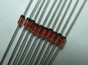
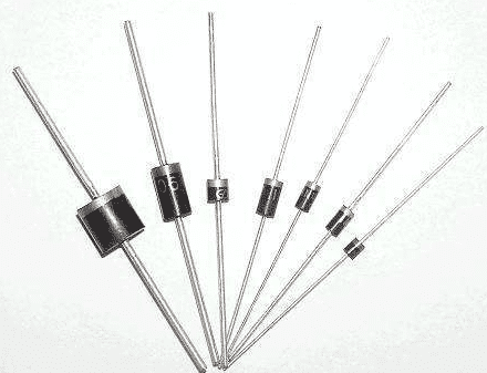
3. Crystal diode
Crystal diode, a semiconductor device at both ends of a solid state electronic device. The main characteristic of these devices is that they have nonlinear current-voltage characteristics. Since then, with the development of semiconductor materials and technology, various kinds of crystal diodes have been developed with different semiconductor materials, doping distribution and geometric structures.
The manufacturing materials are germanium, silicon and compound semiconductor. Crystal diodes are used to generate, control, receive, transform, amplify signals, and convert energy.
A crystal diode is usually represented by a "D" plus a digital representation in a circuit. For example, a D5 represents a 5 diode.
The main characteristic of the diode is unidirectional conductivity, that is, the conduction resistance is small under the action of forward voltage; The conduction resistance is maximum or infinite under the action of reverse voltage.
Due to the above characteristics, the diode is often used in rectifying, isolating, stabilizing, polar protection, coding control, frequency modulation and static noise in cordless telephones. The crystal diodes used in the telephone can be divided into: rectifier diodes (such as 1N4004), isolation diodes (such as 1N4148), schottky diodes (such as BAT85), light emitting diodes, and voltage stabilizer diodes.
Identification of a diode is very simple, small power diode N pole (cathode), in the diode looks mostly adopts a circular color standard, some diodes also use special symbols to represent a P (positive) or N (cathode), also have use symbols for "P", "N" to determine of polarity of the diode. The positive and negative poles of the led can be identified from the length of the pin, the long foot is positive and the short foot is negative.
Test precautions: when using the digital multimeter to measure the diode, the red stylus connects the positive pole of the diode, and the black stylus connects the negative pole of the diode. The measured resistance value is the positive guide resistance value of the diode, which is exactly the opposite of the pointer type multimeter.
The commonly used 1N4000 series diode voltage withstand comparison is as follows: model 1N40011N40021N4003 1N4004 1N40051N40061N4007 voltage withstand (V) 50, 100, 200, 600, 800 1000 current (A) are all 1.
4. Voltage regulator
A voltage-stabilizing diode, also called a zener diode, is a semiconductor device that has high resistance until the critical reverse breakdown voltage.
The voltage regulator diode is usually represented by "ZD" and digital representation in the circuit. For example, ZD5 represents the voltage regulator tube no. 5.
Voltage stabilizing principle of voltage stabilizing diode: the characteristic of voltage stabilizing diode is that the voltage at both ends of it remains basically unchanged after the breakdown. In this way, when the voltage stabilizer tube is connected to the circuit, the voltage at both ends of the load will remain basically unchanged if the voltage at each point of the circuit changes due to power supply voltage fluctuation or other reasons.
Fault features: the fault of the voltage regulator diode is mainly manifested in open circuit, short circuit and unstable voltage value. In these three kinds of faults, the former one shows the power supply voltage increase. The latter two faults are characterized by the power supply voltage being reduced to zero volts or output instability.
The commonly used types and stable voltage values of voltage stabilizer diodes are shown in the following table: type 1N47281N4729 1N4730 1N4732 1N4733 1N4734 1N4735 1N4744 1N4750 1N4751 1N4761
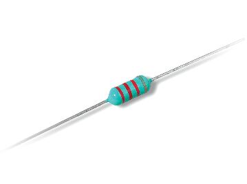
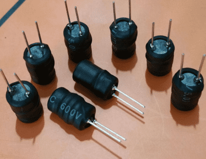
5. Inductance
Inductance is usually represented by "L" and numerals in a circuit. For example, L6 represents inductance numbered 6. Inductor coil is made by winding the insulated wire around a certain number of circles on the insulated frame.
Dc can pass through the coil, dc resistance is the resistance of the wire itself, the pressure drop is small; When the ac signal passes through the coil, both ends of the coil will generate the self-induced electromotive force.
The direction of the self-induced electromotive force is opposite to the direction of the applied voltage, which hinders the passage of the ac. Inductance can form an oscillating circuit with capacitance in a circuit. The inductance usually has the direct mark method and the color mark method, the color mark method and the resistance similar. For example, brown, black, gold and gold represent the inductance of 1uH (5% error).
The basic unit of inductance is: heng (H). The conversion unit is: 1H=103mH=106uH.
6. Varactor Diodes
Variable-capacitance diode, also known as variable reactance diode. It is a kind of diode based on the dependence and principle of p-n junction capacitance (potential barrier capacitance) and its reverse bias voltage Vr. Its structure is shown in the figure on the right.
Tube-capacitance diode is a special diode specially designed according to the principle that the junction capacitance of "PN junction" in a common diode varies with the applied reverse voltage.
In cordless telephone, the variable-capacitance diode is mainly used in the high frequency modulation circuit of mobile phone or landline machine to realize the modulation of low frequency signal to high frequency signal and send it out.
In the working state, the modulation voltage of the variable-capacitance diode is generally added to the negative electrode, so that the internal capacitance capacity of the variable-capacity diode changes with the change of the modulation voltage.
(1) when leakage occurs, the high-frequency modulation circuit will not work or the modulation performance will be poor.
(2) when the variable-capacitance performance is poor, the work of the high-frequency modulation circuit is unstable, so that the high-frequency signal after modulation is sent to the other party after receiving by the other party, resulting in distortion. In one of these cases, the same type of varactor should be replaced.
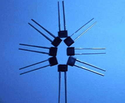
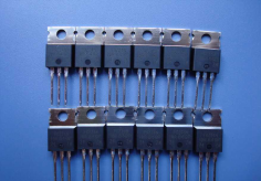
7. Transistor
Transistor transistor, one of the basic components of semiconductor, has the function of current amplification and is the core component of electronic circuit. The triode is to make two PN junction very close to each other on a semiconductor substrate. The two PN junction divide the normal semiconductor into three parts, the middle part is the base area, and the two sides are the transmitting area and the power collection area. PNP and NPN can be arranged in two ways.
The crystal triode is commonly used in the circuit "Q" and digital representation, such as: Q17 for the number 17 triode.
The crystal triode (transistor for short) is a special device with two PN junction inside and amplifying capability. It is divided into two types, NPN and PNP. These two types of transistors can make up for each other in terms of working characteristics. The PNP triode commonly used in the telephone is A92, 9015 and so on. NPN triode: A42, 9014, 9018, 9013, 9012 models.
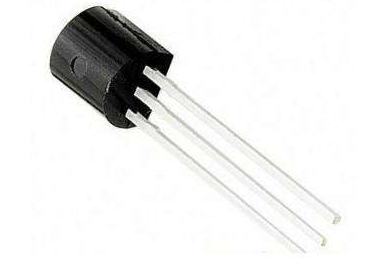
8. Field effect management
A field-effect transistor is a model of transistor. It is commonly used for weak-signal enlargement. And can also be called uni - polar transistor, with higher input obstruction (108 ~ 109 Ω), lower unpitched sound, low capacity using up, big dynamic scope, easy to integrate. The device can amplify analog or digital signals. It can also switch DC or function as an oscillator.
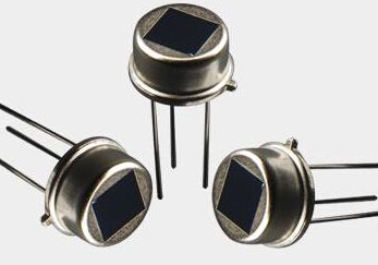
9. Sensors
A sensor is a physical device or biological organ that can detect and sense signals from the outside world, physical conditions (such as light, heat, humidity) or chemical composition (such as smoke), and transmit the detected information to other devices or organs.
The function of sensor is to convert one kind of energy into another form of energy, so many scholars also use "Transducer -Transducer" to refer to "Sensor -Sensor".
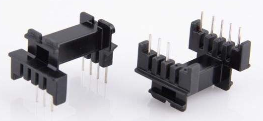
10. Transformer
Transformer is a device that USES the principle of electromagnetic induction to change the ac voltage. Its main components are primary coil, secondary coil and iron core.
In electrical equipment and wireless circuit, it is commonly used as lifting voltage, matching impedance, safety isolation and so on. In a generator, whether the coil moves through magnetic field or magnetic field through a fixed coil, the electric potential can be induced in the coil.
In both cases, the value of magnetic flux remains the same, but the number of magnetic flux in the intersecting chain with the coil is changed, which is the principle of mutual inductance.
A transformer is a device that USES electromagnetic mutual inductance to change voltage, current and impedance. The main functions of the transformer are: voltage conversion; Current change, impedance change; Isolation; Stable voltage (magnetic saturation transformer), etc.