

Home / Industrial Automation low Cost with Arduino an ESP01
Published on 2021/10/10 6:12:54


Components Used in the Project
Description
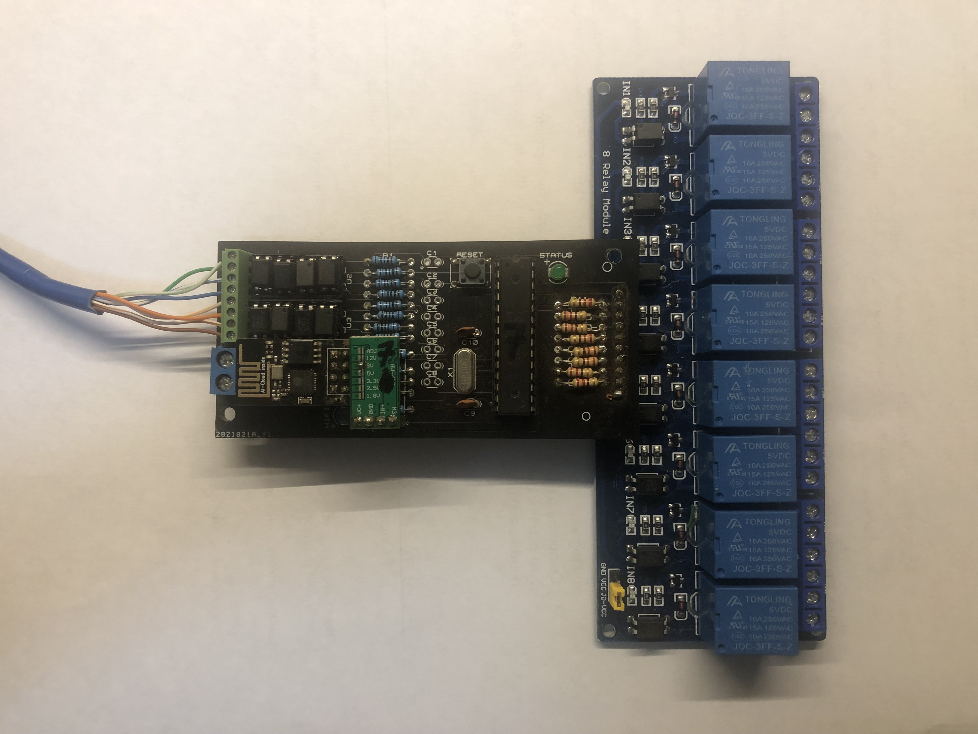
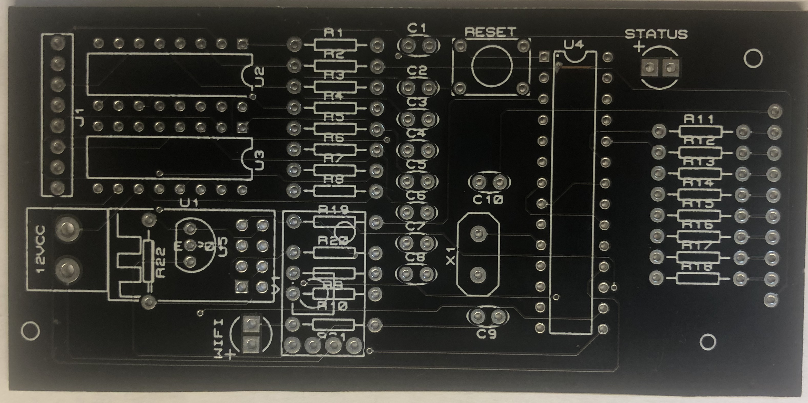
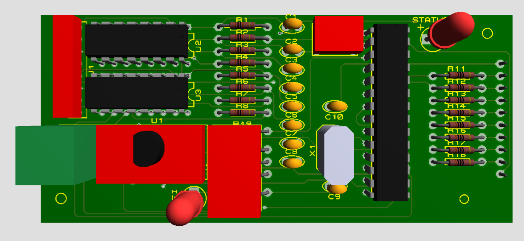
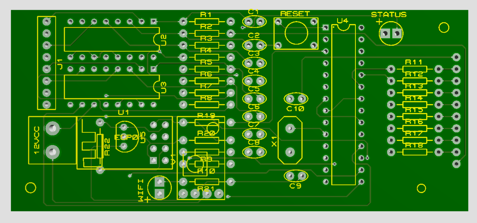
This project was designed for applications with Arduino connected to WiFi, that's why this board is connecting an ATMEGA 328P chip to an ESP01 via serial port, so it is possible to do automation with Arduino and at the same time connect it to WEB applications or MQTT broker (local or in the cloud) cheapest than using a Ethernet Shield. As the intention was a low-cost project, so this board is connected to an 8-relay module to drive dry-contact loads such as lamps and fans. All devices can also be activated locally, as there are also 8 electrically isolated inputs by opto-couplers so that there is no risk of damage to the controller due to a surge, bad contact or induced voltage at the terminals of the switches that will be connected to the controller. In this system it is possible to program the ESP01 to create an internal clock updated by NTP server to trigger loads by scheduled time. Communication with cloud servers is also possible, also enabling access via voice command using smart speakers such as Google Home or Alexa. The user can also create dashboards via app for Android or IOS for remote activation of devices or use a server (with raspberry pi, for example) to access locally with dedicated servers for home automation such as OpenHab, Home Assistant, Domoticz or other of your preference. In Arduino programming, ports A0, A1, A2, A3, A4, A5, 3 and 4 were used for output to the relay module and ports 5, 6, 7, 8, 9, 10, 11 and 12 for the opto-coupled inputs. Pin 13 for the status led (that blink to demonstrate that the program is not locked) and ports 0 (RX) and 1 (TX) for serial communication with ESP01. On the other hand, for ESP01, in addition to configuring NTP to trigger devices by appointment, port 2 was used for the status led (that blink to demonstrate that the program is not locked) in addition to serial communication with the Arduino by GPIO 01 (TX) and GPIO 03 (RX) pins. For the initial tests it was configured to communicate with an MQTT broker running on a Raspberry Pi 3 and it ran perfectly with remote access via OpenHab and also Home Assistant. This board also has a voltage regulator of 3V3 for ESP01 and a 5V for Arduino, so the input power can vary from 6 to 12 volts. It was developed to connect with 8-channel 5V relay modules, but with some adjustments it is possible to connect with 12V modules as well. This project proved to be very efficient for beginning makers who still don't have much domain with the construction of boards, and can only be concerned with the development of software for their small automations.
314
comment
All comments

josemarjr
123123
2021/10/15 13:59:47
comment

josemarjr
123 123 drink 123 123 drink... this project so inspire me thanks for share it
2021/12/9 4:28:45
comment
 josemarjr
1764
2
314
Rules about cashback: 1. Valid time: ALLPCB cashback activity will end on April 1st. 2. Capped amount: The capped amount of cashback for each account is $5,000. Each order can get a maximum of $2,000 cashback. That means every author can get $5,000 max. 3. Cashback range: The cashback activity only covers the corresponding PCB order. The order amount for other combined payment products will be invalid. 4. Clicking your own promotional link will be invalid. The same email address, shipping address, contact information, and phone number are all recognized as the same account. 5. ALLPCB has the final interpretation right of the cashback activity.
ALLPCB will donate 2% to the author for this promotion link.